A control valve is a power-operated device used to regulate or manipulate the flow of fluids, such as gas, oil, water, and steam.
It is a critical part of a control loop and is an example of a final control element. The Control Valve is by far the most common final control element used in industry today.
Control valve actuator
A control valve can be operated electrically, pneumatically, or hydraulically.
A control valve receives a signal from a controller such as a PLC in order for it to move resulting in a change in flow.

Because the PLC signal is electrical, the control valve may require a device to convert that electrical signal so that it can operate.

A control valve has two separate components: the Valve and the Actuator.

Control valve body
Valve bodies are of different types or styles depending on service conditions, piping layout, and desired application.
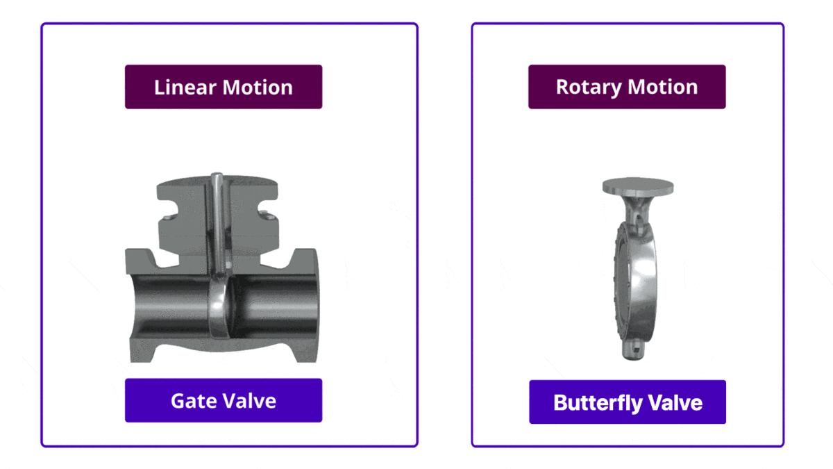
The two classes of control valves are Linear Motion and Rotary Motion.

Butterfly valve vs. Gate valve
On a linear motion valve, the stem and valve movement is up and down. A common type of sliding control valves is the Gate Valve.
A rotary motion valve in almost all cases rotates 90° from open to the closed position. A commonly used rotary valve is the Butterfly Valve.
Control valve operation
The actuator is the device connected to the valve through the valve stem that provides the force required to move the valve.
As we said earlier, the actuator can be controlled electrically, pneumatically, or hydraulically. The most common and the most reliable is the “Pneumatic Actuator”.
The control valve receives a signal from a controller such as a PLC or a DCS in order to operate. The controller compares the actual flow rate to the desired flow value called the setpoint. The controller will produce an output to move the valve to bring the flow rate to the setpoint value.

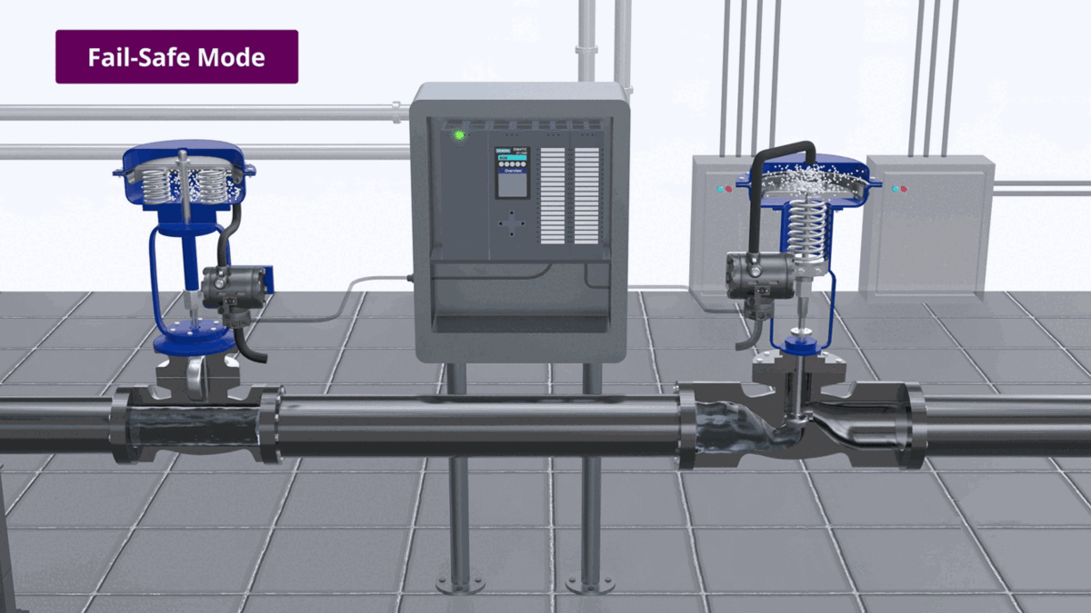
Control valve fail-safe mode
Because of how pneumatic actuators are built, a control valve will fail to a specific position when a loss of the control signal occurs.
As the supply air pressure is increased, the rubber diaphragm pushes against the spring and moves the valve stem down into the valve body.
As the supply air pressure is reduced, the spring will move the valve stem out of the body.
The position to which the control valve is moved if a loss of signal occurs is referred to as the fail-safe mode. The type of fail-safe mode depends on the application for which the control valve is used.
The actuator causes the valve to close in a Fail-Closed Control Valve.
The actuator causes the valve to open in a Fail-Open Control Valve.
In normal operation, the force of the spring must be overcome by the electrical or pneumatic actuator.
In the event of a power failure to the actuator, the electrical or pneumatic force is no longer present and the spring pressure forces the valve to open.
